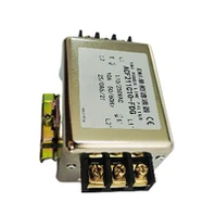
In the realm of electronics, electromagnetic interference (EMI) is a persistent challenge that can disrupt the normal operation of electronic devices. EMI filters play a crucial role in mitigating this interference, ensuring the smooth and reliable performance of various electrical systems. One of the key characteristics of an EMI filter is its frequency response curve, which provides valuable insights into the filter's ability to attenuate unwanted electromagnetic signals across different frequencies. As an EMI filter supplier, understanding the frequency response curve is essential for designing and delivering high - quality filters that meet the specific needs of our customers.
Understanding the Basics of an EMI Filter
Before delving into the frequency response curve, it's important to have a basic understanding of what an EMI filter is. An EMI filter is an electrical device designed to suppress electromagnetic interference by allowing the desired frequencies (usually the operating frequencies of the equipment) to pass through while attenuating the unwanted frequencies. It consists of passive components such as inductors, capacitors, and resistors, which are arranged in a specific circuit configuration to achieve the desired filtering effect.
EMI filters are widely used in a variety of applications, including power supplies, industrial equipment, telecommunications devices, and automotive electronics. In power supplies, for example, EMI filters can reduce the noise generated by the switching action of the power converter, preventing it from being transmitted to the connected equipment or the power grid. In industrial equipment, they can protect sensitive electronic components from external electromagnetic interference, ensuring the reliability and accuracy of the equipment's operation.
What is a Frequency Response Curve?
A frequency response curve is a graphical representation of how a system, in this case, an EMI filter, responds to different frequencies. It shows the relationship between the input frequency of an electrical signal and the output amplitude (or attenuation) of the signal after passing through the filter. The horizontal axis of the curve represents the frequency, usually plotted on a logarithmic scale, ranging from a few hertz to several gigahertz. The vertical axis represents the attenuation in decibels (dB), which is a measure of how much the filter reduces the amplitude of the input signal at a particular frequency.
The shape of the frequency response curve is determined by the design and component values of the EMI filter. Different types of filters, such as low - pass, high - pass, band - pass, and band - stop filters, have distinct frequency response characteristics.
Low - Pass Filters
A low - pass filter allows low - frequency signals to pass through while attenuating high - frequency signals. Its frequency response curve shows a relatively flat region at low frequencies, where the attenuation is minimal, and a steep slope at high frequencies, where the attenuation increases rapidly. Low - pass filters are commonly used in power supply applications to remove high - frequency noise from the DC output.
High - Pass Filters
In contrast, a high - pass filter allows high - frequency signals to pass through and attenuates low - frequency signals. The frequency response curve of a high - pass filter has a steep slope at low frequencies and a relatively flat region at high frequencies. High - pass filters are often used in audio applications to remove low - frequency noise, such as hum.
Band - Pass Filters
A band - pass filter allows a specific range of frequencies (the passband) to pass through while attenuating frequencies outside this range. Its frequency response curve has a peak in the passband, where the attenuation is minimal, and slopes on either side of the passband, where the attenuation increases. Band - pass filters are used in communication systems to select a specific frequency band for transmission or reception.
Band - Stop Filters
A band - stop filter, also known as a notch filter, attenuates a specific range of frequencies (the stopband) while allowing frequencies outside this range to pass through. The frequency response curve of a band - stop filter has a dip in the stopband, where the attenuation is high, and relatively flat regions outside the stopband. Band - stop filters are used to remove unwanted frequencies, such as interference from a specific radio station.
Importance of the Frequency Response Curve for EMI Filters
The frequency response curve is of utmost importance for EMI filters for several reasons. Firstly, it helps in evaluating the performance of the filter. By analyzing the curve, we can determine the frequencies at which the filter provides the desired level of attenuation. For example, if an application requires attenuation of high - frequency noise above 10 MHz, we can check the frequency response curve to ensure that the filter provides sufficient attenuation in this frequency range.
Secondly, the frequency response curve is used in the design process. When designing an EMI filter, engineers need to select the appropriate components and circuit configuration to achieve the desired frequency response. They can use simulation tools to predict the frequency response curve of the filter based on the component values and then adjust the design to optimize the performance.
Thirdly, the frequency response curve is essential for matching the filter to the specific application. Different applications have different EMI requirements, and the frequency response curve can help us choose the right filter for the job. For instance, a power supply for a sensitive medical device may require a filter with a very low - pass frequency response to ensure that it does not introduce any electromagnetic interference to the device.
Factors Affecting the Frequency Response Curve
Several factors can affect the frequency response curve of an EMI filter.
Component Values
The values of the inductors, capacitors, and resistors in the filter circuit have a significant impact on the frequency response. For example, increasing the value of an inductor in a low - pass filter will shift the cutoff frequency (the frequency at which the filter starts to attenuate the signal) to a lower value, resulting in a steeper slope in the attenuation region.
Component Tolerances
The tolerances of the components can also affect the frequency response curve. Components with larger tolerances may cause variations in the actual frequency response compared to the designed curve. This is especially important in high - precision applications where tight control of the frequency response is required.
Parasitic Effects
Parasitic effects, such as the stray capacitance and inductance of the components and the printed circuit board (PCB), can also alter the frequency response curve. These parasitic effects can introduce additional poles and zeros in the filter transfer function, which can change the shape of the curve and reduce the filter's performance at high frequencies.
Load Impedance
The load impedance connected to the output of the EMI filter can affect the frequency response. A mismatched load impedance can cause reflections, which can distort the frequency response curve and reduce the attenuation performance of the filter.
Our EMI Filter Offerings
As an EMI filter supplier, we offer a wide range of filters with different frequency response characteristics to meet the diverse needs of our customers. Our 3 Phase Ac Filter is designed for three - phase power applications and provides excellent attenuation of common - mode and differential - mode noise across a wide frequency range. The frequency response curve of our 3 - phase AC filter is carefully optimized to ensure that it meets the strict EMI requirements of industrial and commercial power systems.
Our 3 Phase Filter is another popular product, which is suitable for various three - phase electrical equipment. It has a well - defined frequency response curve that can effectively suppress electromagnetic interference in the power lines, protecting the connected equipment from damage and ensuring its reliable operation.


We also offer Rfi Emc Filter, which is specifically designed to address radio - frequency interference (RFI) and electromagnetic compatibility (EMC) issues. These filters have a frequency response curve that provides high attenuation in the radio - frequency range, making them ideal for applications such as telecommunications, wireless devices, and broadcasting equipment.
Contact Us for Procurement
If you are in need of high - quality EMI filters for your application, we are here to help. Our team of experienced engineers can work with you to understand your specific EMI requirements and recommend the most suitable filter based on the frequency response curve and other performance parameters. Whether you are looking for a standard filter or a custom - designed solution, we have the expertise and resources to meet your needs.
Contact us today to start a procurement discussion. We look forward to partnering with you to solve your EMI challenges and ensure the reliable operation of your electronic systems.
References
- "Electromagnetic Compatibility Engineering" by Henry W. Ott
- "Filter Design Handbook" by Arthur B. Williams and Fred J. Taylor
- "EMI/EMC for Product Designers" by Tim Williams