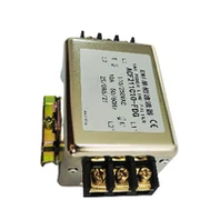
As a supplier of 3 PHASE FILTERS, understanding how to measure the attenuation rate of these filters is crucial. This knowledge not only helps us in product development and quality control but also enables us to provide accurate information to our customers. In this blog post, I will share the methods and considerations for measuring the attenuation rate of a 3 PHASE FILTER.
Understanding the Basics of 3 PHASE FILTERS
Before delving into the measurement of the attenuation rate, it's essential to have a basic understanding of 3 PHASE FILTERS. A 3 PHASE FILTER is designed to suppress electromagnetic interference (EMI) in three - phase electrical systems. It helps to ensure the proper functioning of electrical equipment by reducing unwanted noise and interference.
There are different types of filters in our product range, such as 3 Phase Emc Filter, 4 - line Filters, and Signal Line Filter. Each type has its own characteristics and applications, but the principle of measuring the attenuation rate is similar.
What is Attenuation Rate?
The attenuation rate of a filter refers to the ability of the filter to reduce the amplitude of a signal at a specific frequency. It is usually expressed in decibels (dB). A higher attenuation rate means that the filter can more effectively suppress the interference signal. For example, if a filter has an attenuation rate of 30 dB at a certain frequency, it means that the amplitude of the interference signal at that frequency is reduced to 1/10 of its original value.
Measuring Equipment
To measure the attenuation rate of a 3 PHASE FILTER, we need the following equipment:
- Network Analyzer: A network analyzer is a key instrument for measuring the attenuation rate. It can generate a signal with a specific frequency and measure the input and output amplitudes of the filter. By comparing the input and output amplitudes, we can calculate the attenuation rate.
- Cables and Connectors: High - quality cables and connectors are required to ensure accurate signal transmission between the network analyzer and the filter.
- Power Supply: A stable power supply is needed to power the filter during the measurement process.
Measurement Setup
- Connect the Equipment: First, connect the network analyzer to the input and output ports of the 3 PHASE FILTER using appropriate cables and connectors. Make sure the connections are secure to avoid signal loss or interference.
- Configure the Network Analyzer: Set the frequency range and step size according to the measurement requirements. For example, if we want to measure the attenuation rate from 10 kHz to 100 MHz, we can set the start frequency to 10 kHz, the stop frequency to 100 MHz, and the step size to an appropriate value, such as 100 kHz.
- Calibration: Before starting the measurement, it is necessary to calibrate the network analyzer to eliminate the influence of the cables and connectors. This can be done by performing a short - open - load calibration.
Measurement Process
-
Generate the Signal: The network analyzer generates a signal with a specific frequency and sends it to the input port of the filter.
-
Measure the Input and Output Amplitudes: The network analyzer measures the amplitude of the input signal and the output signal of the filter.
-
Calculate the Attenuation Rate: The attenuation rate (A) can be calculated using the following formula:
[A = 20\log_{10}\left(\frac{V_{in}}{V_{out}}\right)]
where (V_{in}) is the amplitude of the input signal and (V_{out}) is the amplitude of the output signal. -
Repeat the Measurement: Repeat the above steps for different frequencies within the set frequency range to obtain the attenuation rate curve of the filter.
Considerations
- Environmental Factors: The measurement environment should be free from strong electromagnetic interference to ensure the accuracy of the measurement results. It is recommended to perform the measurement in an anechoic chamber or a shielded room.
- Load Conditions: The attenuation rate of the filter may be affected by the load connected to its output port. Therefore, it is necessary to measure the attenuation rate under different load conditions to obtain a more comprehensive understanding of the filter's performance.
- Measurement Accuracy: To improve the measurement accuracy, multiple measurements can be taken and the average value can be calculated. In addition, high - quality measurement equipment should be used, and regular calibration should be carried out.
Interpreting the Results
The attenuation rate curve obtained from the measurement can provide valuable information about the performance of the 3 PHASE FILTER. A good filter should have a high attenuation rate in the frequency range where interference is likely to occur. For example, in a power system, the filter should have a high attenuation rate in the frequency range of 150 kHz to 30 MHz to suppress conducted EMI.
If the measured attenuation rate does not meet the requirements, it may be necessary to adjust the design of the filter, such as changing the values of the components or the structure of the filter.
Application in Product Development and Quality Control
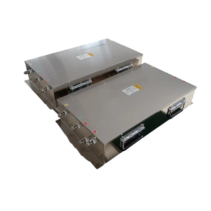
As a 3 PHASE FILTER supplier, the measurement of the attenuation rate is an important part of product development and quality control. During the product development process, we can use the measurement results to optimize the design of the filter and improve its performance. In the quality control stage, we can use the attenuation rate as an important indicator to ensure that the products meet the quality standards.

Conclusion
Measuring the attenuation rate of a 3 PHASE FILTER is a complex but essential process. By using the appropriate equipment and methods, and considering various factors, we can obtain accurate measurement results. These results can not only help us in product development and quality control but also provide our customers with reliable information about the performance of our filters.
If you are interested in our 3 PHASE FILTER products or have any questions about the attenuation rate measurement, please feel free to contact us for procurement and further technical discussions.
References
- "Electromagnetic Compatibility Engineering" by Henry W. Ott.
- "Filter Design Handbook" by Don Lancaster.